Rocketry Experience
Most team members have firsthand experience with high-power rocketry, having participated in events with Tulsa Rocketry and gained insights from seasoned rocket enthusiasts at launches. Additionally, ten students have successfully built a LOC IV Level 1 high-power rocket, scheduled for launch on November 9th and 16th (rescheduled due to burn bans, weather conditions, and Tulsa Rocketry’s availability). All team members have been trained in essential high-power rocketry components and simulation software, including OpenRocket and RASAero II.
Each rocket build required approximately 20 hours of dedicated work per member. This included applying epoxy, adding internal and external fillets, installing recovery systems, and performing quality checks at every stage. Through this hands-on process, students developed essential skills in rocket construction, learned about recovery techniques, and gained a deep understanding of stability-critical assembly practices.

One of our team members, a master’s student, brings extensive personal experience in high-power rocketry. They attended their first NAR/Tripoli-sanctioned club launch with Tulsa Rocketry in June 2020, following years of building Estes model rockets. In July 2020, they flew a Madcow Sport-X on an H148R to 1,700 feet, achieving their Level 1 certification. Since then, they have participated in major events, including Airfest, where they have attended each annual event since 2020. Building on their initial certification, they progressed to dual-deployment rockets, starting with a Mach-1 BT56 mid-power fiberglass kit capable of housing a single Eggtimer Quark altimeter.

In late 2021, this student began constructing a Level 2-capable Ibex 54 fiberglass rocket from Composite Warehouse. After a successful test flight at Airfest 28 in 2022, the Ibex flew on an I284W motor to 4,200 feet, paving the way for their Level 2 certification attempt. The certification was successfully completed later that month at High Frontier in Pawhuska, OK, with a flight to 5,700 feet on a J350W motor. Since achieving their Level 2 certification, they have flown motors up to a J450DM and reached altitudes of up to 6,720 feet with a 38mm fiberglass minimum diameter rocket.
In addition to rocket construction, this team member has extensive experience in altimeter bay design, redundancy, safety, and recovery. They have also designed and tested custom fly-away rail guides, which have been successfully used on rockets ranging from lightweight 18mm models to larger, 8-inch rockets exceeding 40 pounds.
Through this breadth of experience, the master’s student contributes invaluable expertise in high-power rocketry, enriching the Hurricane Rocketry Club’s capabilities and furthering the team’s goals in competitive rocketry.
STEM Outreach Events

Our club recently engaged with a local elementary school, providing an interactive experience where 36 fifth- and sixth-grade students built and launched paper rockets. This aligns with our club’s mission to offer aerospace-related experiences to both our members and the broader community. Looking ahead, we plan to conduct model rocket launches with low power rocket motors for older students in local schools, aiming to inspire a lasting interest in rocketry and a potential passion for STEM. Please see our social media or website to learn more.
Rocket Logistics
- Total Vehicle Length: 2.21 meters
- Airframe Diameter: 102 mm
- Fin-span: 101.6 mm
- Vehicle weight only: 7.68 kgs
- Propellent weight: 2.52 kgs
- Payload weight: 2 kgs
- Total Liftoff weight: 12.2 kgs
- Number of stages: 1
- Total Vehicle Length: 7.25 feet
- Airframe Diameter: 4.02 inches
- Fin-span: 4 inches
- Vehicle weight only: 17 lbs
- Propellent weight: 5.6 lbs
- Payload weight: 4.41 lbs
- Total Liftoff weight: 26.9 lbs
- Number of stages: 1
Structural Integrity Calculations
Fin flutter calculations assumed the following environmental conditions:
- Launch Altitude: 4,945 ft
- Temperature: 90°F
- Shear Modulus of G10 Fiberglass: 600,000 psi
- Maximum Velocity and Altitude at Maximum Velocity: Derived from RASAero II simulations
These conditions reflect realistic values expected during the flight, allowing us to closely approximate in-flight forces acting on the fins.
The Fin flutter velocity equation is show below:

A table of available G10 fiberglass thicknesses was generated, each evaluated for its corresponding safety margin.
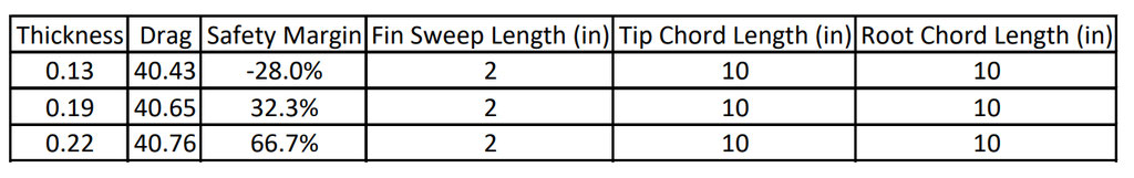
The drag was calculated as a proportion in reference to the fin parameters, with a focus on reducing overall drag without compromising safety

We selected the 3/16-inch fins for their cost-effectiveness and lightweight properties, while maintaining a safety margin above 25%
The team conducted an optimization study of this thickness to identify optimal parameters for the root chord, tip chord, and sweep length of the rocket’s fins. These parameters were selected to maximize the fin’s resistance to flutter while minimizing drag. The target safety margin was set at 25% to provide a conservative buffer against potential material variability and environmental factors.
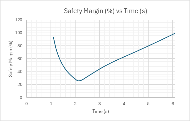
Using the optimized fin parameters, we plotted safety margin as a function of time. Notably, there is a brief period (approximately 0.4 seconds) where the safety margin dips below 30%. Although this period is brief, additional analysis will be required to verify that structural integrity is maintained. We plan to conduct shear analysis tests to evaluate the material’s structural performance and validate the assumed shear properties.
Propulsion System
- Propulsion Type: solid
- Propulsion manufacturer: commercial
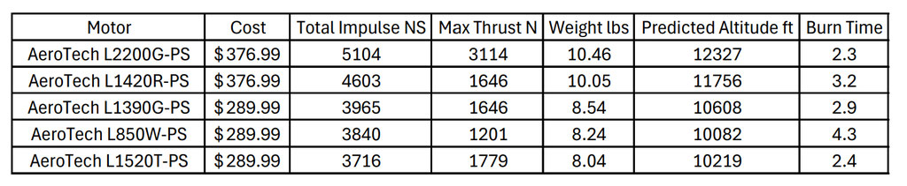
- Total Impulse of all Motors: 5104 Ns
From the outset, we aimed for an L2 motor to achieve the target apogee, designing the rocket specifically with this motor class in mind. For motor selection, we focused exclusively on Aerotech, leveraging our experience with their range of readily available, prebuilt motors in RASAero II. We narrowed down our search to high-performance L2 motors, then optimized for altitude to allow flexibility in adjusting rocket mass during testing. Ultimately, we selected the L2200G-PS, which met all criteria while being cost-effective.
Simulated Flight Data and Analysis
- Launch Rail: ESRA Provided Rail
- Rail Length: 5.7 meters
- Liftoff Thrust-Weight Ration: 23.37
- Launch Rail Departure Velocity: 47.85 meters/second
- Minimum Static Margin During Boost: 1.84
- Maximum Acceleration: 26.96 G
- Maximum Velocity: 393.77 meters/second
- Target Apogee: 10,000 feet
- Predicted Apogee: 12,327 feet excluding added mass
The rocket model was initially designed in OpenRocket and subsequently imported into RASAero II to conduct more detailed simulations, particularly for the supersonic flight regime. Since an active airbrake device is not incorporated, altitude control will be achieved by adding mass to the rocket to reach the target apogee of 10,000 feet. Accurate mass adjustments require simulations with minimal error in predicting apogee. To reduce this error, we will experimentally determine the rocket’s drag coefficient through repeated test launches and calculate the optimal mass needed to achieve the desired altitude. Accordingly, the rocket has been designed to exceed the 10,000-foot target in simulation, allowing for precise adjustments based on drag characterization.
Payload Project
The atmospheric turbulence experiment employs a commercial wavefront sensor (Thorlabs WFS series) connected to a Raspberry Pi microcomputer for assessing turbulence intensity at different levels of the atmosphere. The wavefront sensor uses a detector array combined with a fly’s eye lens array to spatially sample light propagating through the atmosphere from a light source (here, the sun). Voltage signals from each detector component are then collected by the microcomputer at a moderate sample rate, typically on the order of 10,000 samples per second to capture the millisecond time scales for turbulent phenomena. Statistical analysis of the samples in both space (across the array) and in time provides the means to estimate the refractive index structure constant (Cn2), which indicates the level of turbulence present.
The microcomputer is housed within the rocket’s payload bay, mounted on a removable 3D-printed nylon sled alongside the power source. A USB cable passes through the rocket’s exterior to connect the microcomputer to the wavefront sensor, which is secured to the rocket’s exterior using a dedicated mounting element. A small encasement would provide physical protection and limit the viewing window to a specific direction. A color filter placed over the aperture of the camera will limit measurement to a small visible wavelength range. Both the encasement and the filter will improve the quality of the measurement process. A small piece of software running on the microcomputer would perform data collection. Data will be extracted and used for Dr. Lopresti’s research at the University of Tulsa
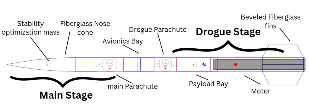
The payload bay consists of two interconnected inner tubes, each fitted with bulkheads featuring ¼-20 threaded inserts (McMaster-Carr #3313N127) to securely fasten the payload within the rocket. The aft bulkhead’s threads are fixed with weld nuts and epoxy, while the forward bulkhead is secured with accessible ¼-20 nylon nuts (McMaster-Carr #90648A029). The 3D-printed nylon sled is mounted within these threaded inserts, ensuring the stability of all electronic components.
Electronics
Our primary altimeter is the EggTimer Quasar, chosen as it offers an affordable solution that meets all functional requirements. Based on recommendations from experienced members of the Tulsa Rocketry Club, this altimeter is widely used and highly reliable. The Quasar is designed to handle supersonic conditions, aligning well with our mission requirements.
The Quasar utilizes a barometric sensor for altitude measurement with timestamps, eliminating the need for an accelerometer. Although the sample rate is lower than some alternatives at 30 samples per second, this rate is sufficient for our purposes, as data collection is not our primary objective. Deployment is ignited by the Quasar’s two pyro outputs. However, it draws slightly more power than comparable models, which we have factored into our circuit and avionics bay design.
The Quasar also features an integrated GPS transmitter, allowing us to track the rocket’s position without needing a separate GPS unit, reducing overall costs. For redundancy, we selected the EggTimer Quantum altimeter, which provides similar functionalities minus the GPS transmitter, making it a cost-effective backup.
To power our altimeters, we will use two 2S/7.4V LiPo batteries with a 900 mAh capacity from URGENEX. These batteries are connected to the altimeters via arming switches. Each altimeter will be equipped with two commercial off-the-shelf (COTS) e-matches, one for deploying the drogue parachute and the other for the main parachute.
For position tracking, the EggTimer Quasar’s built-in GPS transmitter links to the EggTimer LCD Handheld Receiver, which operates on the 900 MHz band without a license and can also operate on the 70 cm ham band if required. As a backup for GPS redundancy, we opted for a small radio beacon that does not require a license, as this is sufficient for secondary tracking needs.
Recovery
Our rocket is equipped with a doubly redundant dual-deploy recovery system. It utilizes two altimeters—the Eggtimer Quantum and Quasar—each powered by its own lithium polymer battery pack. These batteries have nearly double the manufacturer’s recommended capacity, ensuring that voltage remains stable throughout the flight. Each altimeter independently controls black powder charges for the drogue and main parachutes, with the Quantum programmed to deploy a short interval after the Quasar, providing redundancy in case of primary system failure. At the launchpad, each altimeter is armed separately, and their Wi-Fi functionality allows for operational status checks prior to launch. Both altimeters will transmit continuous telemetry to the ground, allowing us to monitor flight performance and determine maximum altitude for competition scoring.
To minimize drift, we have chosen a dual-deploy recovery approach. The first separation event occurs at apogee, deploying the drogue chute, with a backup deployment two seconds later. The second event occurs at 700 feet, deploying the main chute, with a redundant activation 100 feet lower.
Based on an estimated pressure of 15 psi required for separation and reducing the ideal gas law to our controllable variables of diameter and length, we calculate that for a 4” diameter rocket with a 10” compartment to pressurize, we will need 0.96g of black powder for the initial drogue and main ejection charges. Our backup charges will be 1.5x that amount, to ensure that if something prevented the rocket from separating on the initial event, the parachutes still deploy. Therefore, our backup drogue and main charges will be 1.44g of black powder.
Given 12.5 square inches to pressurize with a 4” diameter, our primary charges will generate around 188 pounds of force and our backup charges will generate 282lbs of force. We will use 3 2-56 nylon shear pins to provide enough strength to hold the nose cone and payload bay to the avionics bay and prevent premature separation. Since each pin can hold up to 35lbs of force, only 105lb of force would be needed to break them, ensuring that we have at least 1.5x the necessary amount force.
Extensive ground testing in full launch configuration will be used to verify our estimate. Additional black powder may be added as needed to ensure complete separation.
Our 3/16″ bulkhead is designed to withstand the deployment forces. It is reinforced with a U-bolt securely fastened to the bulkhead, connecting to a stainless steel quick link (McMaster-Carr #8947T27), rated for 2,400 pounds. The quick link’s 3/8″ opening is large enough to accommodate our 0.14″ diameter shock cord. This shock cord, a flame-resistant 2,800-pound-rated braided Kevlar line from Rocketman, is selected for its durability and resistance to burn-through. Following standard guidelines, the shock cord length is set at three times the rocket length, making it at least 21 feet for our rocket.
For descent control, the drogue parachute is a 30.56″ diameter hemispherical chute from Spherachute with an estimated CD of 1.33, attached approximately 60” along the shock cord, ensuring a stable descent configuration. The maximum descent velocity prior to main chute deployment is 58.13 feet per second. The main parachute 107″ diameter, also a hemispherical design with estimated CD of 1.33 from Spherachute, ensures a controlled ground impact velocity of 15.9 feet per second. The hemispherical chute was selected for its high drag, strength, and minimal drift, providing stability without excess weight.
Planned Test: January 2025 (1)
- Type: Ejection charge
- Description: Using a portable launch controller, we will test each ejection charge and verify the rocket rocket separates fully so the parachutes can be deployed
- Status: Not started
- Comments: Test will be conducted outside in a clear area
Planned Test January 2025 (2)
- Type: Altimeter igniter
- Description: Using the set bench testing for the igniter, we will verify the igniter will be fired
- Status: Not started
- Comments: The altimeter will be heavily researched
- Date: January 2025
- Type: Altimeter Pressure reading
- Description: Using a vacuum chamber and syringe, we will simulate the rocket launch. Using a Jolly Logic AltimeterOne included with the rocket altimeter inside the vacuum chamber, we will verify the accuracy of the altimeter by comparing the read altitude from the Jolly Logic AltimeterOne once the igniter is fired and the expected altitude. Additionally, we will verify both igniters fire.
- Status: Not started